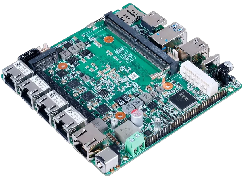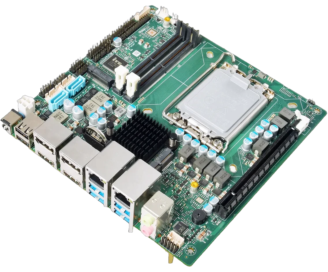
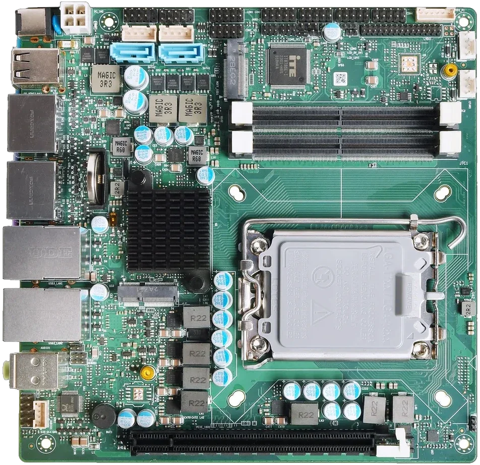
170 × 170 mm
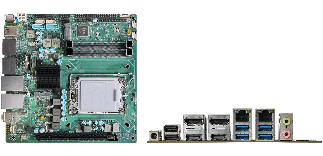
ITX660B
PCIe 4.0 ×16, 65 W TDP and 12–24 V. A review base for accelerator or multi-display nodes. The 170 mm outline leaves room for a card.

Capability / Engineering and DFM
Board selection, carrier and thermal review, connector and enclosure fit, and DFM before tooling. Reviews are scoped per project, and the review is a document, not a conversation.
Reviews are scoped per project; no fixed review turnaround is published until confirmed. Manufacturing is by Piesia.
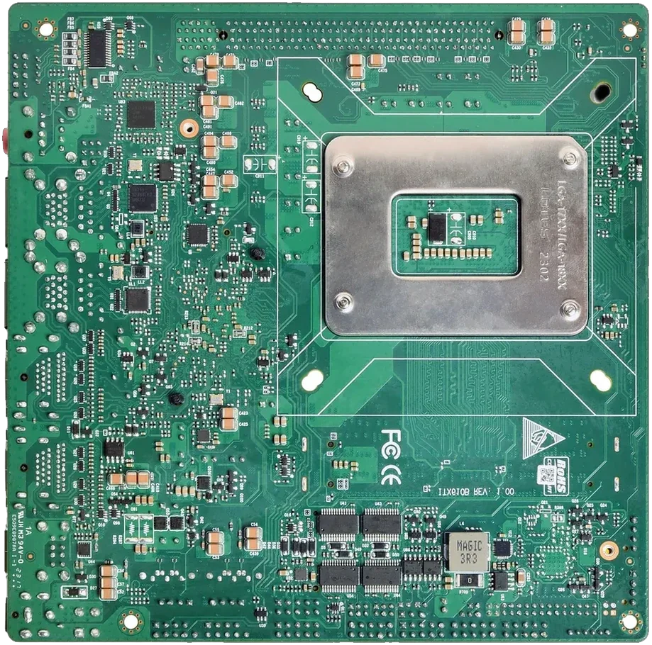
The review order / what can invalidate a design
A dimension error is cheaper to find before tooling. Each item below has a drawing or note behind it.
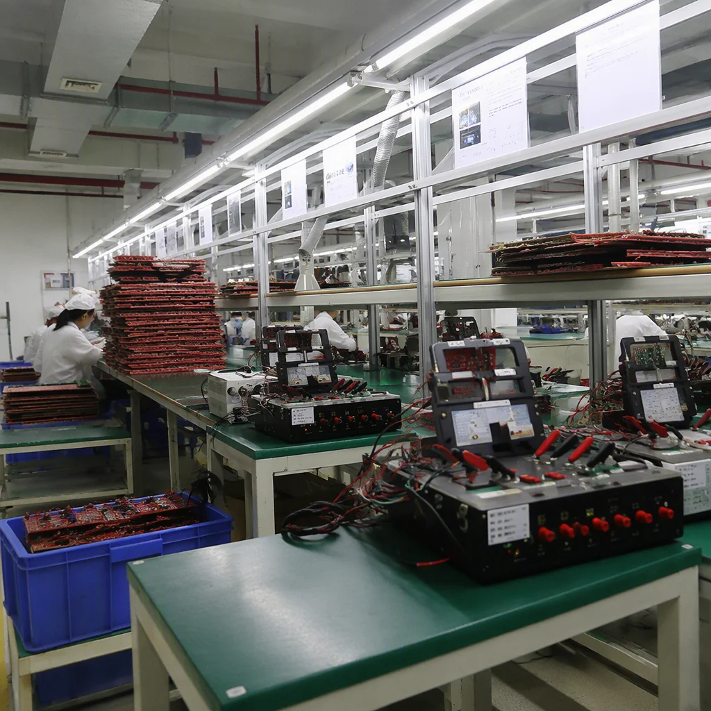
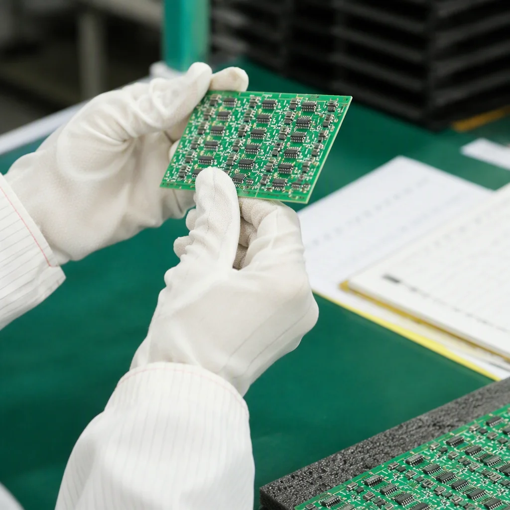
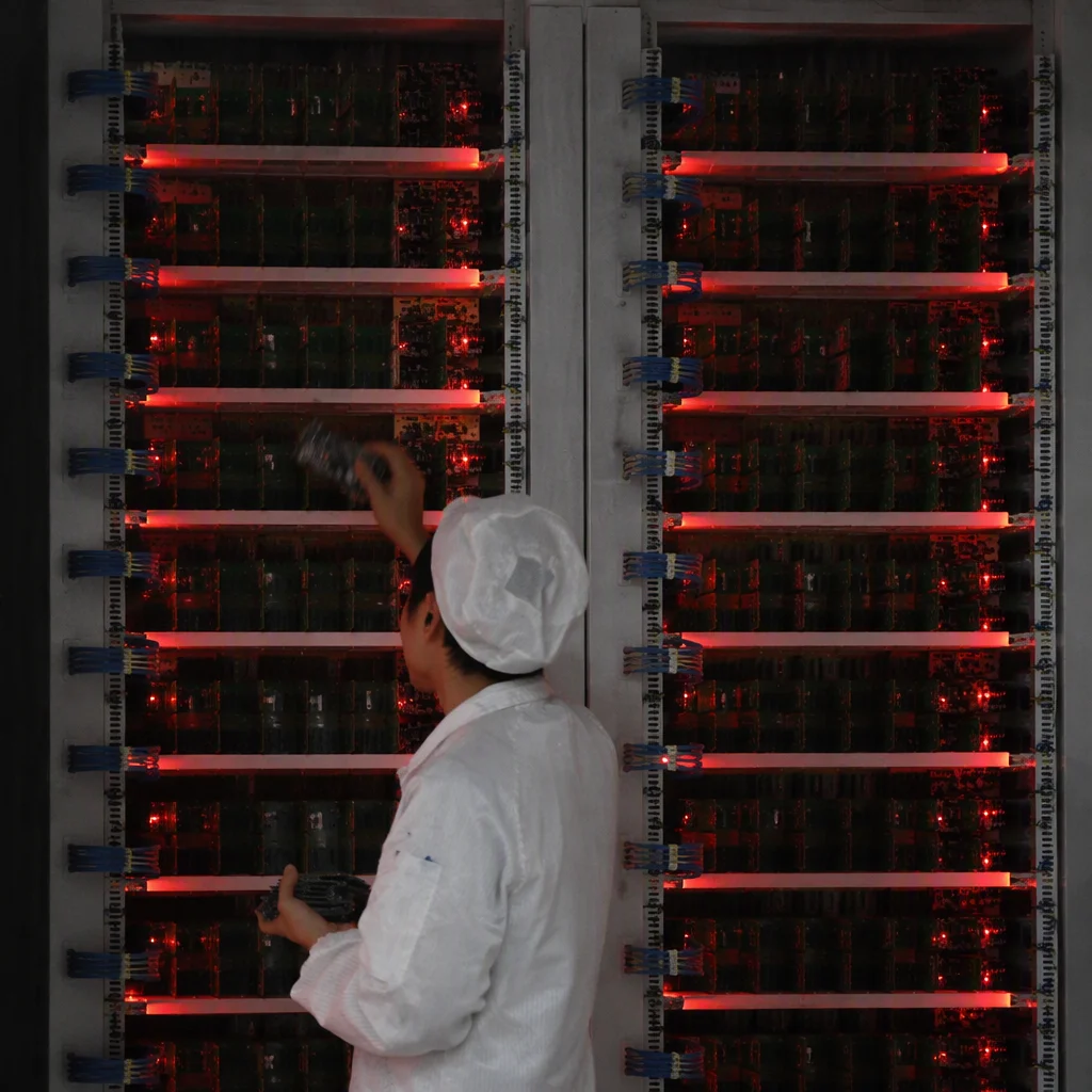

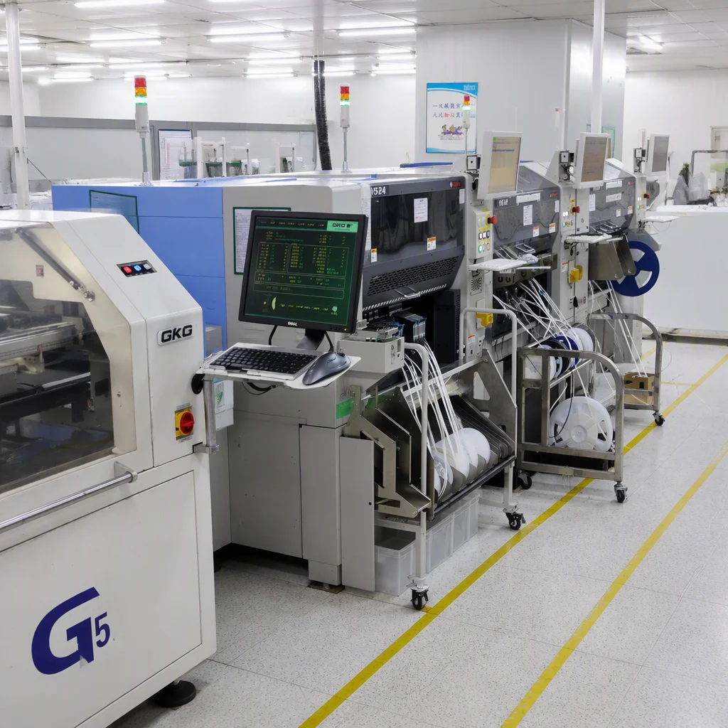
Five gates, one document set. Drawing and note per gate.
Review sequence / five gates
Each gate has a deliverable; the next gate starts when it closes. A gate can send the design back one step.
Outline, keep-outs and fastener positions against the enclosure drawing. The 170 mm board does not fit a 155 mm opening.
Heatsink height, airflow direction and the sustained CPU tier. A 28 W part in a sealed box may run lower.
Plug heights, bend radius and service access. Service access is part of the fit.
Panelisation, tooling and assembly before the sample is released. Panel and fixture review comes first.
First article for fit and function, checked against the request.
Dimension stack / drawn to scale
The drawing is to scale; the labels are the catalog values.
Scroll to see all six outlines.
Risk to review step
| Risk | Gate | Deliverable |
|---|---|---|
| Mounting conflict | Envelope and mounting | Keep-out and fastener drawing |
| Thermal throttling | Thermal path | Heatsink and airflow note |
| Connector clash | Connector and cable exit | Cable-exit drawing |
| Tooling rework | DFM | Tooling review |
| Sample mismatch | Sample | First-article check |
Review bases / three models
The outline difference decides the first question.
PCIe 4.0 ×16, 65 W TDP and 12–24 V. A review base for accelerator or multi-display nodes. The 170 mm outline leaves room for a card.
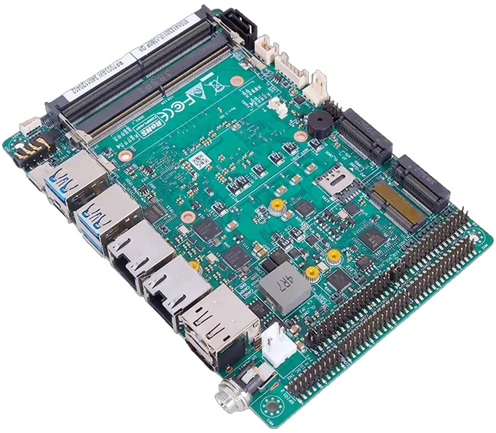
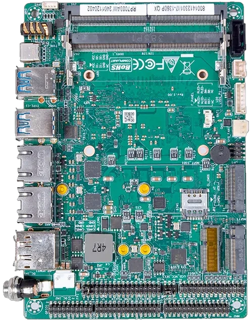
Two CAN headers, M.2 B-Key and 9–36 V. A review base for DIN-rail gateways. The 146 mm outline suits a compact gateway enclosure.
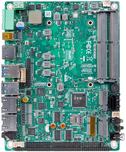
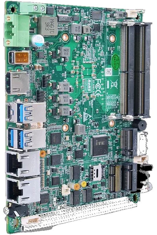
28 W, 9–36 V and LVDS/eDP. A review base for panel-PC and kiosk enclosures. The 155 mm outline sits between the two sizes.
Before the review
Yes, as a scoped review. Send the drawing, the board choice and the thermal load; the review is confirmed per project. A 3D model shortens the review.
Board model or form factor, enclosure drawing, connector list and operating range. A 3D model helps if you have one.
No fixed review turnaround is published until confirmed. Certification of the finished equipment stays with the integrator.
Engineering and DFM / scoped inquiry
Reviews are scoped per project. Include the target enclosure material. Quote within 24–48 h; open terms confirmed at quotation.
Manufacturing is by Piesia. No fixed review turnaround is published until confirmed.
 Illustrative scene