Does this apply to my model?
Dimensions are catalog values; hole patterns and connector positions are checked per model.

Design guide 01 / enclosure fit
The board you choose is the space you give it. Compare the six catalog envelopes at one scale, then check mounting, connector height and heatsink clearance.
170 × 170155 × 117146 × 102120 × 120100 × 100100 × 72mm
True-scale outlines
All six outlines are drawn at the same scale. Dimensions are catalog values; 28 models sit inside these six envelopes.
Enclosure check / four measurements
Dimensions decide the footprint; four checks decide whether the board goes in.
A 146 × 102 mm board with a 25 mm heatsink needs more internal depth: the outline is a footprint, not a clearance.
Six form factors
| Form factor | Dimensions | DC input | Expansion | COM / LAN | Cooling | Models |
|---|---|---|---|---|---|---|
| 2.5-inch | 100 × 72 mm | 12 V | M.2 M-Key | 2 / 1 | Fan optional | 4 |
| 3.5-inch | 146 × 102 mm | 9–36 V | M.2 + SATA | up to 6 / 2 | Heatsink | 4 |
| 3.5-inch Wide | 155 × 117 mm | 9–36 V | M.2 + SATA + CAN | 6 / 2 | Heatsink | 2 |
| NANO-ITX | 120 × 120 mm | 9–36 V | M.2 per model | up to 5 / 4 | Fanless | 5 |
| NUC | 100 × 100 mm | 12–19 V | M.2 + SATA | USB / 1–2 LAN | Fanless | 6 |
| Mini-ITX | 170 × 170 mm | 12–19 / 24 V | PCIe on some models | up to 6 / 2 | Heatsink/fan | 7 |
Selection order / four cuts
The envelope removes the most options first; temperature and lifecycle decide the final model.
Model shortlist / one per envelope
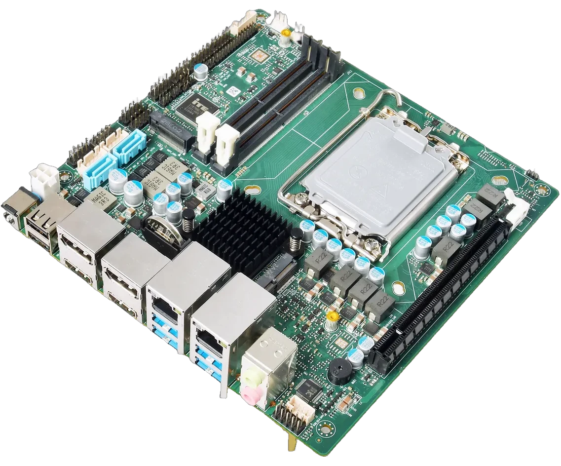
 AD742A
2.5-inch · 100 × 72 mm
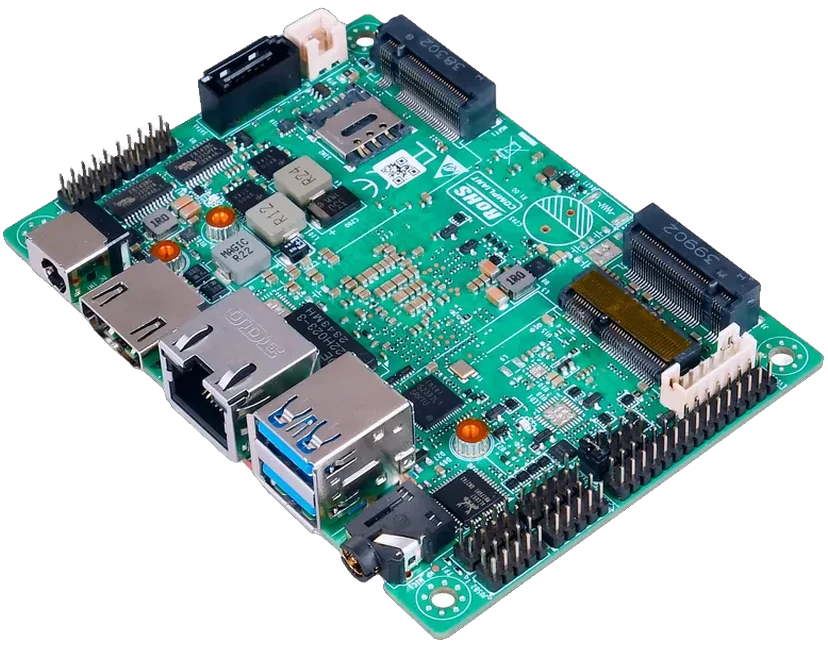
 MSK-TL5003AW
3.5-inch · 146 × 102 mm
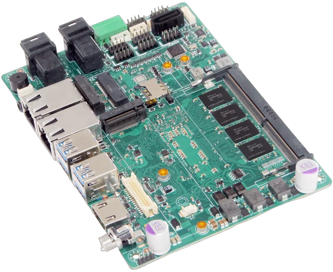
 AD600Z3AW
3.5-inch Wide · 155 × 117 mm
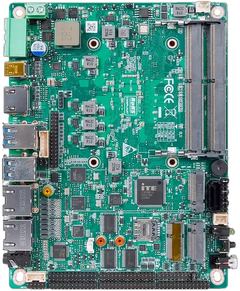
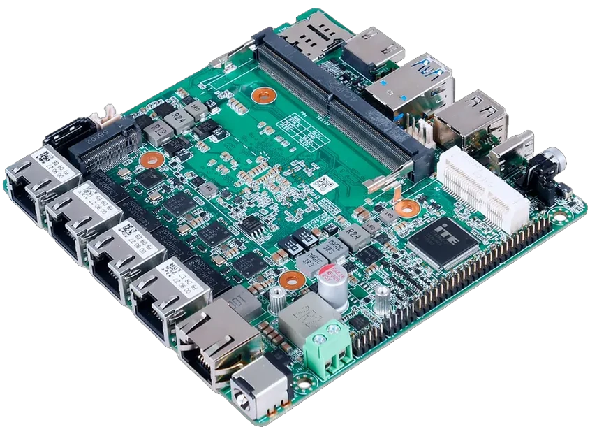 PNM-5210
NANO-ITX · 120 × 120 mm
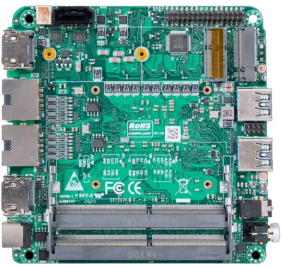 AD600CA
NUC · 100 × 100 mm
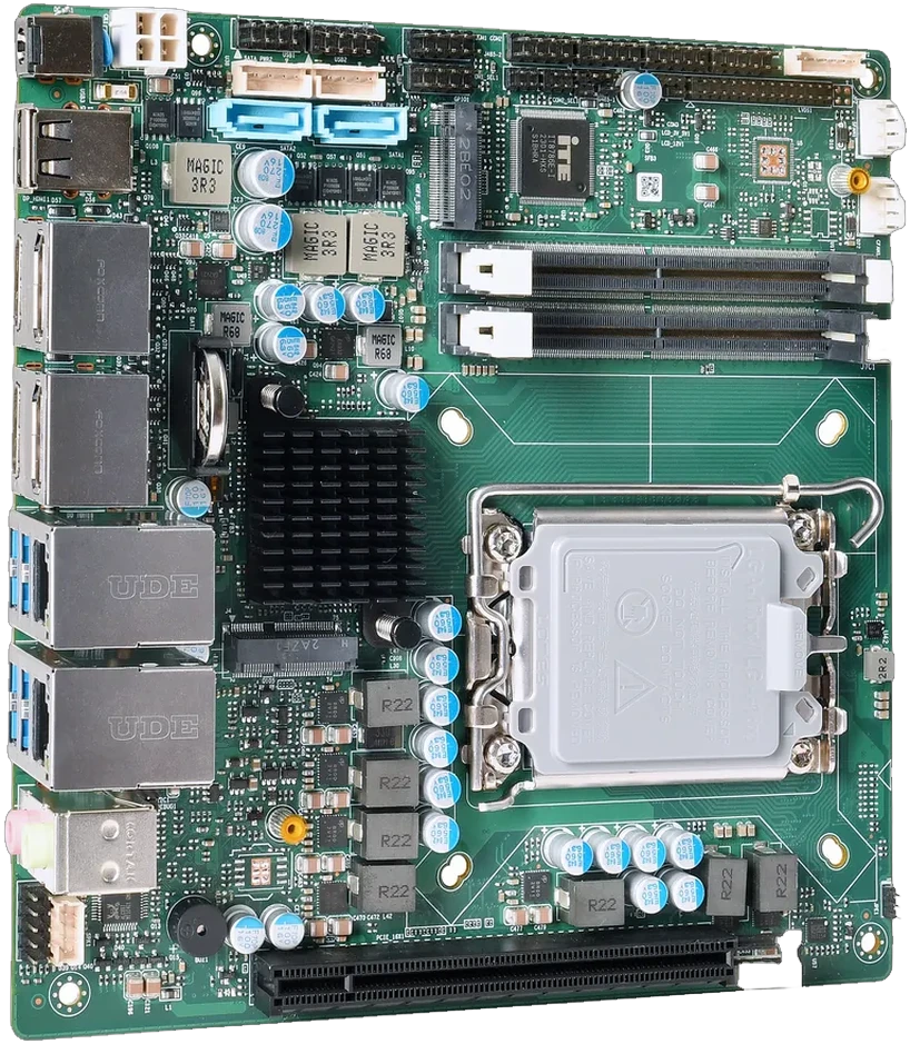 ITX660B
Mini-ITX · 170 × 170 mm
One model per envelope; the catalog holds 28. Ask for the spec card before layout freeze.
Edge detail / what the outline hides
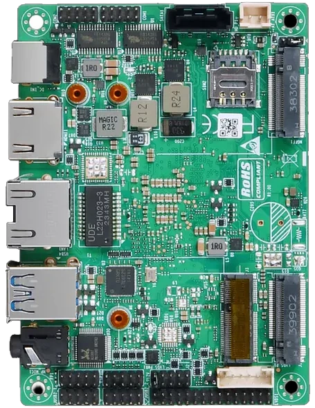
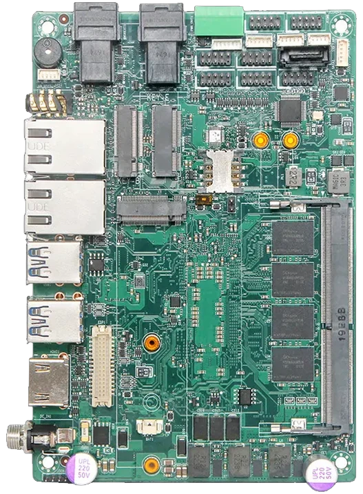
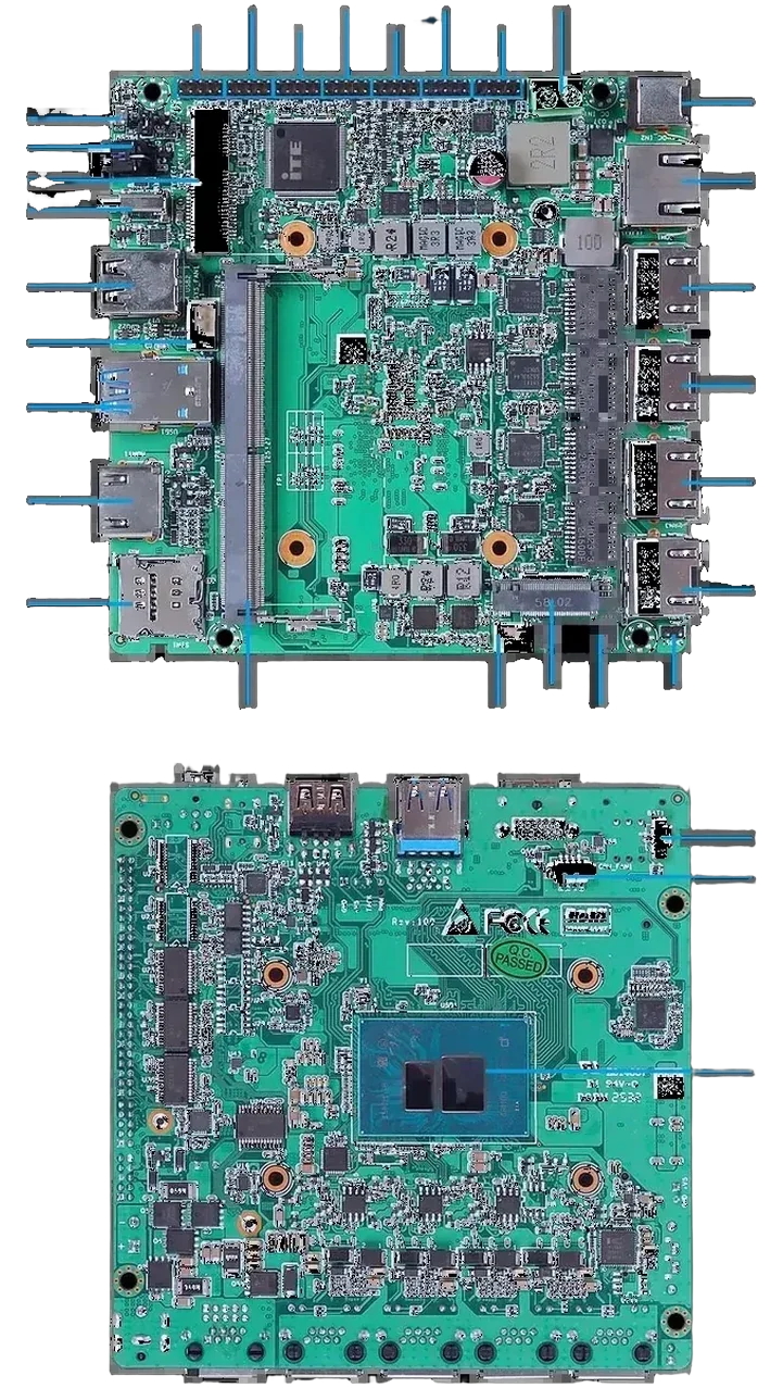
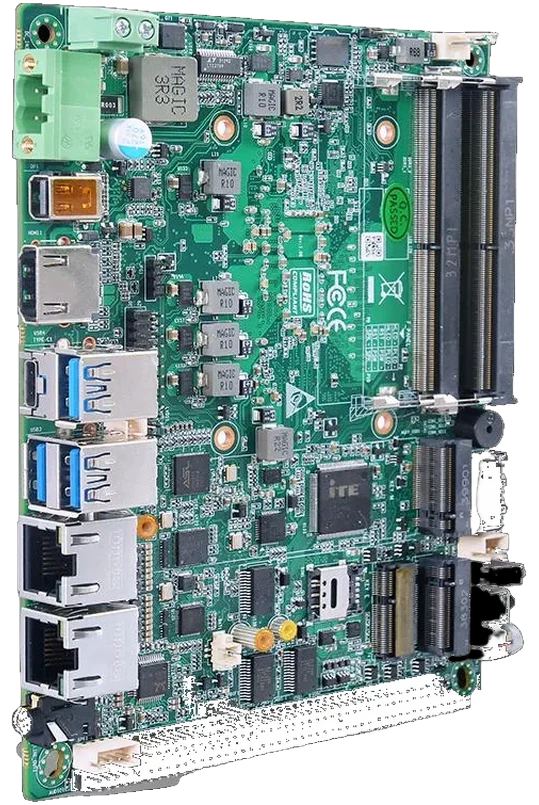
Boundary / board vs system
The catalog gives the envelope and the board rating. The enclosure, airflow path and finished-system validation stay with the integrator.
Before the shortlist
Dimensions are catalog values; hole patterns and connector positions are checked per model.
No protection level is stated on the spec cards; confirm it before design freeze.
Hole pattern, connector height, cable exit, heatsink clearance and enclosure temperature.
Next step / model shortlist
Send the internal envelope, connector height and operating range for the closest model. Quote within 24–48 h.